A pouch cell looks simple: a thin aluminium-laminate envelope, two tabs and a high ratio of active material to packaging. That low-overhead format is one reason pouch cells are attractive for industrial drones. Yet the flexible case also removes a structural function that cylindrical and rigid prismatic cells partly provide for themselves. The surrounding battery pack must hold the pouch cell correctly as it breathes, relaxes and ages.
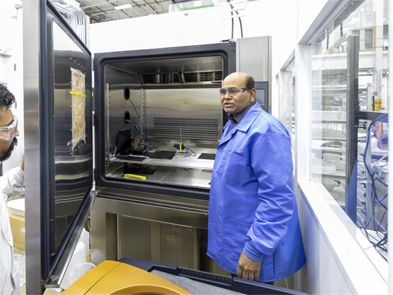
Figure 1. Oak Ridge National Laboratory’s Batteries at Extreme Conditions Lab simulates high-power, thermal and mechanical stressors relevant to aviation. This is a research facility, not a commercial UAV pack test. Courtesy of Oak Ridge National Laboratory, U.S. Dept. of Energy. Official ORNL source
This is where pouch-cell stack pressure becomes a hidden design variable. Too little pressure can allow contact to deteriorate and swelling to become uneven. Too much can restrict ion transport, redistribute electrolyte and promote lithium plating. Recent 2026 research makes the message unusually clear: the best result sits inside a cell-specific pressure window—not at the loosest or tightest setting.
Why a flexible pouch needs mechanical support
Lithium-ion electrodes change dimensions as lithium moves in and out of their active materials. Some thickness change is reversible during charge and discharge. Other growth is irreversible and can come from solid-electrolyte interphase formation, gas generation, particle damage or lithium plating. A flexible pouch transmits those changes to its surroundings instead of hiding them behind a rigid can.
Correct support keeps the broad cell faces in controlled contact while leaving seals and tabs free from harmful loads. It also helps maintain the intended thermal interface. In a drone pack, that support must be lightweight, vibration-resistant and stable across temperature, state of charge and ageing. A foam pad, spring plate or bolted frame that feels firm at assembly may deliver a very different pressure after weeks of relaxation or hundreds of cycles.
Pressure is a window, not a universal number
The phrase “correct pressure” should mean a validated operating range for a specific cell and mission—not a copied value from another paper. Chemistry, electrode loading, silicon content, separator, electrolyte amount, pouch dimensions, temperature and current profile all change the mechanical-electrochemical balance. The pack mechanism then determines how that pressure evolves as the cell thickness changes.
Pressure must also be defined carefully. Cell-face pressure is force divided by loaded area. Clamp force is the total force delivered by the hardware. Bolt torque is only an indirect assembly input; friction, plate bending, fastener position and pad compression can all make the real pressure non-uniform. A specification that says only “tighten to 1 N·m” does not tell a buyer what the pouch cell actually experiences.
What the latest 2026 experiment found
A Nature Energy study published in 2026 tested approximately 210 mAh graphite‖single-crystal NMC811 pouch cells under controlled constant pressure. The cells were cycled at C/3 and 26°C between 2.8 and 4.6 V after formation. Three highlighted conditions were 3 bar, 12.5 bar and 37.5 bar [1].
The average cycle count to 80% capacity retention was 169 cycles at 3 bar and 161 cycles at 37.5 bar. At 12.5 bar, the cells remained above 80% after more than 375 cycles. In other words, both pressure extremes delivered less than half the demonstrated life of the optimized condition in that experiment. The first-cycle discharge capacities differed by no more than 2.7%, so a short incoming inspection could easily miss the long-term divergence [1].
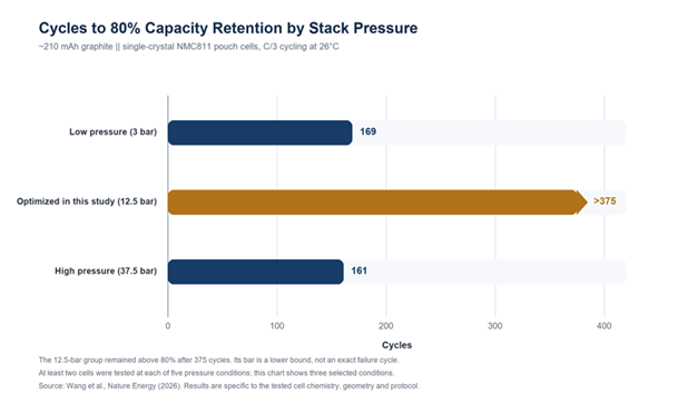
Figure 2. Published cycle-life results for three selected stack-pressure conditions from the five pressure levels evaluated. At least two cells were tested at each pressure condition. The >375-cycle value is right-censored: the optimized group had not yet reached 80% capacity retention. This chart is a redrawing from reported numerical results, not a reproduction of the publisher’s figure. Peer-reviewed data source
The mechanisms were different at the two extremes. Under low pressure, the researchers observed stronger irreversible expansion, a thicker aged anode and evidence consistent with disconnected graphite and cathode cracking. Under high pressure, the cell initially compacted, then showed accelerated irreversible expansion; post-mortem analysis found signs of lithium plating and transport limitations associated with reduced porosity and electrolyte displacement. The optimized-pressure cells maintained a more stable thickness and more homogeneous electrode condition [1].
Critical limitation: 12.5 bar is the optimum reported for this small NMC811 pouch cell and this test protocol. It is not a recommended setpoint for a large UAV cell or pack.
Why the number cannot be copied into a drone pack
A second 2026 peer-reviewed study examined large-format pouch cells at practical high current, using 1C charge and 2C discharge. Unconstrained cells initially offered more accessible depth of discharge, but faded faster, developed more resistance and ran hotter. External pressure improved lifetime and heat removal, yet excessive constraint also produced ionic-transport limitations and inhomogeneous lithiation. In that study, a reduced-pressure condition provided the best compromise [2].
The apparent conflict is valuable. One study found an optimum around 12.5 bar in a small, high-voltage NMC811 cell; another favored reduced pressure in a large-format commercial cell. Together they support the same engineering conclusion: the optimum belongs to the cell, loading and test conditions. A battery supplier should provide its own validation instead of presenting one academic pressure as a universal specification.
| Pressure state | Potential benefit or balance | What may fail |
| Too low | Less initial pore restriction; mechanical support remains insufficient. | Contact loss, uneven swelling, cracking and rising resistance. |
| Validated window | Contact, transport and thickness control are balanced. | The window can move with cell design, temperature, rate and ageing. |
| Too high | Face contact and heat transfer may improve initially. | Pore restriction, electrolyte redistribution, lithium plating and seal stress. |
Evidence summary based primarily on Wang et al. [1] and Hölderle et al. [2]. Effects are cell- and protocol-dependent.
A small pressure value can mean a large clamp force
Pressure becomes real hardware through F = pA. Consider a 100 × 150 mm loaded cell face, an illustrative area of 0.015 m². At 1 bar, the required force is 1.5 kN. At 3 bar, it is 4.5 kN. At 12.5 bar, it would be 18.75 kN—roughly 1.9 metric-ton-force. These calculations are not design recommendations. They show why a pressure demonstrated on a 20 × 35 mm laboratory cell cannot simply be transferred to a much larger aerial battery.
For UAV engineers, the hardware penalty matters. Thick plates improve uniformity but add mass; thin plates save mass but can bow between fasteners. Springs improve compliance but consume volume. Foam distributes load, but its preload can change as the pad relaxes over time [5]. Compression hardware must therefore count toward pack-level Wh/kg.
Constant pressure and fixed gap are not the same
A fixed-gap frame holds a nominal distance. As cells relax, shrink or swell, the force can change substantially. A spring system converts displacement into a smaller, more predictable force change. A pneumatic or bellows fixture can actively maintain pressure, although it is usually a laboratory tool rather than flight hardware.
A 2025 comparative study tested fixed-displacement, coil-spring and pneumatic fixtures. The fixed-displacement design showed high pressure variation and significant loss during a 48-hour relaxation test from an initial 90 kPa. Spring and pneumatic constant-pressure devices performed better, with the pneumatic concept benefiting from active control but adding complexity [3]. In the 2026 Nature Energy setup, a custom bellows design limited fluctuations below 0.8%, compared with about 6% for spring-loaded and about 20% for bolted fixtures characterized by those researchers [1]. These values describe their fixtures, not every bolt or spring design.
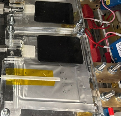
Figure 3. Real instrumented pouch cells held between acrylic plates in a 2026 University of Warwick study. The bolts and plates provide a boundary condition, but bolt torque alone does not define a uniform cell-face pressure. Cropped from Figure 4 of Sunil et al.; the crop is a layout adaptation. Source paper · CC BY 4.0
Swelling is not one phenomenon
Thickness change can come from reversible electrode breathing or irreversible gas and material growth. Treating both as the same “swelling” signal can lead to a poor control strategy. A 2026 Journal of Energy Storage paper introduced direct internal gas-pressure measurement in laboratory pouch cells. It showed that internal pressure varies with state of charge, electrical and thermal loading, and cell chemistry; the researchers separated reversible lithiation-related changes from gas generation during formation [4].
This distinction matters in a drone pack. A compliant pad may safely accommodate normal reversible motion, while a persistent increase after rest may signal ageing or gas generation. Conventional BMS measurements of voltage, current and surface temperature do not directly reveal face-pressure distribution. Future high-value UAV packs may combine these signals with strain, force or thickness sensing, but the sensor must not puncture the pouch, concentrate stress or create false confidence from one measurement point.
What changes in an industrial drone
Aerial batteries face a combination that most cell papers do not reproduce: high take-off current, vibration, changing cooling airflow, low-temperature operation, payload-dependent duty cycles and a hard landing reserve. Pressure that looks acceptable during a slow room-temperature cycle may become non-uniform when the frame flexes, the pack heats or the aircraft vibrates.
The design should also protect the pouch perimeter. Broad-face compression is different from loading the heat-sealed edge, pulling on tabs or pinching a cell over a fastener. A structurally efficient UAV pack supports the active face, isolates the tab-to-busbar joint from cable motion, provides an expansion allowance and preserves a thermal path without blocking inspection. Replaceable packs also need repeatable clamping after service; a mechanism that depends on technician feel is difficult to control across a fleet.
A practical validation plan for a custom UAV battery
A credible programme connects material science to the aircraft mission. The following sequence is more useful than quoting one “optimal” pressure from the literature:
- Define the cell-level window. Test multiple pressure levels across the intended state-of-charge, temperature and C-rate range. Report the loaded area, fixture type and whether pressure is constant or displacement-controlled.
- Map pressure uniformity. Use calibrated pressure film or a sensor array to identify plate bowing, fastener hot spots, edge loading and cell-to-cell variation. A single central force reading is not a uniformity map.
- Measure pressure drift. Record relaxation after assembly, reversible change during cycling and irreversible growth with age. Include foam compression set, spring travel and plate deflection.
- Run the real mission profile. Reproduce take-off, climb, hover, cruise, payload manoeuvre and landing reserve at relevant temperatures. Track cell voltage, temperature, thickness or force and pack energy simultaneously.
- Add aviation mechanics. Repeat electrical tests after vibration, shock and thermal cycling. Inspect pouch seals, tab joints, insulation, pads and fasteners before declaring the pressure system stable.
- Confirm at pack and aircraft level. State aircraft model, take-off mass, payload, weather, flight mode and landing reserve. Cell-fixture cycling cannot prove flight endurance or fleet life by itself.
What buyers should request from a supplier
Ask first whether the quoted value is cell-face pressure, total clamp force, foam compression or bolt torque. Request the loaded area and pressure distribution, not only an assembly drawing. The supplier should state the conditions used to define the range: cell model and batch, chemistry, state of charge, temperature, C-rate, cycle count and rest time.
Then ask how the pack maintains pressure. Is it fixed-gap, spring-loaded, foam-buffered or another compliant design? What are the plate flatness and stiffness assumptions? How much cell growth can it accept before seals, tabs or neighbouring cells are overloaded? Is the compression hardware included in pack mass and energy-density claims? What changes after foam ageing, fastener relaxation or cell replacement?
Finally, request evidence at three levels: cell cycling under controlled pressure, complete-pack testing under the mission current and temperature profile, and aircraft flight data with a stated reserve. A high-quality answer will separate measured results from models and will report unsuccessful pressure conditions as well as the best one. That transparency is more valuable than an impressive but context-free pressure number.
Where pouch-pressure design is heading
The next generation of drone battery packs is likely to use lighter constant-force structures, better compression-pad models and pressure-aware health diagnostics. Digital twins may combine current, temperature, impedance and mechanical response to distinguish normal electrode breathing from persistent gas or damage. Production systems can also verify plate flatness, pad thickness and clamp force instead of relying only on final pack voltage.
The commercial opportunity is not to make every pack tighter. It is to make the mechanical boundary condition traceable. For long-endurance, inspection and heavy-payload UAVs, reliable energy delivery depends on chemistry, electronics, thermal management and mechanics working together. A high-energy pouch cell cannot deliver its laboratory promise if the pack lets it move too freely—or squeezes it past its transport limits.
Conclusion
Pouch-cell compression is not secondary packaging. It is part of the electrochemical operating environment. The latest evidence shows a clear U-shaped risk: insufficient and excessive pressure can both shorten life through different degradation pathways, while a validated middle window can stabilize thickness, contact and transport.
For industrial drone developers and battery buyers, the right question is not “How many bar is best?” It is “What pressure window has been validated for this cell, this pack mechanism and this mission—and how uniform and stable is it over life?” When that question is answered with traceable data, the flexible pouch format can deliver its real advantage: high packaging efficiency without sacrificing repeatability in the air.
References
[6] Oak Ridge National Laboratory. Batteries at Extreme Conditions Lab. Updated 18 November 2025.